Home
IoT Lightsensor
Lorem ipsum dolor sit amet, consectetur adipiscing elit, sed do eiusmod tempor incididunt ut labore et dolore magna aliqua. Ut enim ad minim veniam, quis nostrud exercitation ullamco laboris nisi ut aliquip ex ea commodo consequat. Duis aute irure dolor in reprehenderit in voluptate velit esse cillum dolore eu fugiat nulla pariatur. Excepteur sint occaecat cupidatat non proident, sunt in culpa qui officia deserunt mollit anim id est laborum.
Worked all Germany contest 2015
This was my first participation in the WAG contest since 2010 - and I must say, it was a pleasure!
I managed to complete 472 QSOs all in CW :-)
SOTA - DM/BW-094 - Kornberg
![]() My second SOTA activation is done. Monika (DL6SCF) and I made a short hiking trip on the Swabian Alps. On top of the Kornberg we made a stop and started the activation ... unfortunately we have to shut down operation due to a rising thunderstorm.
My second SOTA activation is done. Monika (DL6SCF) and I made a short hiking trip on the Swabian Alps. On top of the Kornberg we made a stop and started the activation ... unfortunately we have to shut down operation due to a rising thunderstorm.
IoT MQTT Infrastructure
Since the beginning of my home automation project I made several tests to choose the right platform and right controller. I've done test with various sensor technologies etc. etc.
Most of the articels can be found in the Arduino category.
One decision was, that my webhost should be the main datastore for all data measured. With this decision, I've started to build a data collection and distribution infrastructure. The complete setup consists of two major components:
These components are detailed further down the page.
SOTA - DM/BM-344 - Kleiner Kulm - My first activation is done
![]() During a business trip, I took the chance to activate a mountain in the Bavarian low mountains - Kleiner Kulm.
During a business trip, I took the chance to activate a mountain in the Bavarian low mountains - Kleiner Kulm.
Read more: SOTA - DM/BM-344 - Kleiner Kulm - My first activation is done
Frog sounds - How far can you hear a frog croak?
Currently I've done 6 QSOs with the Frog and my dipole antenna.
Frog sounds - The frog has arrived
Yesterday I've build the FROG SOUNDS 40m CW QRP transceiver.
I've ordered it as a kit from eBay Seller for about €10,- inclusive shipping to DL. The kit arrived well packed after about 15 days in my postbox.
ELECRAFT K2 - Fixing VFO ALC issue
I've planned to sell my ELECRAFT K2 so I placed some adds in the various HAM sources and I found a buyer willing give my K2 a new home.
Fortunately I decided to do a quick check on the K2 functions, to be sure, that the buyers receives a full functional K2.
I did the check in the late afternoon on 80m and I was shocked - strong stations can be received every 7kHz. Testing the transmitter shows a totally unstable RF signal.
vna/J ist umgezogen
Alle Informationen bezüglich vna/J sind auf eine neue Webseite umgezogen:
vna/J moved to a new location
All information regardung vna/J is moved to my new site
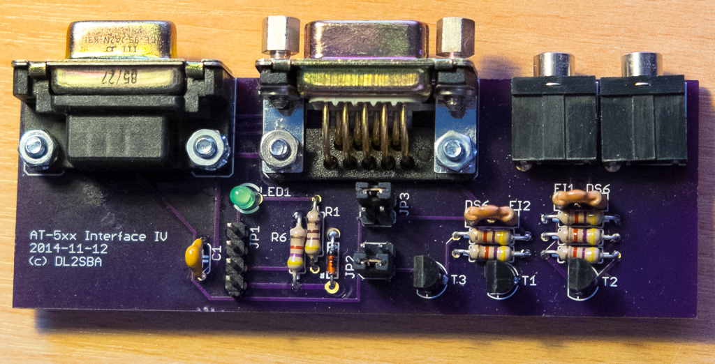
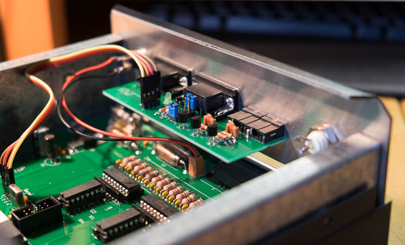
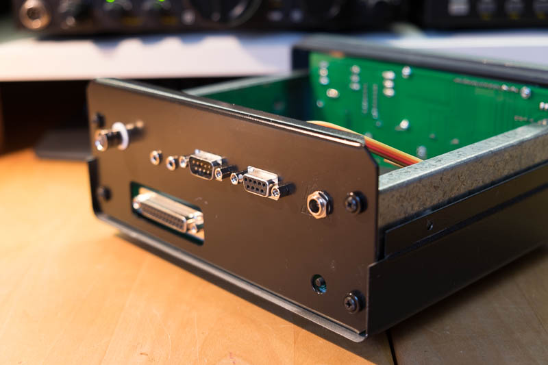
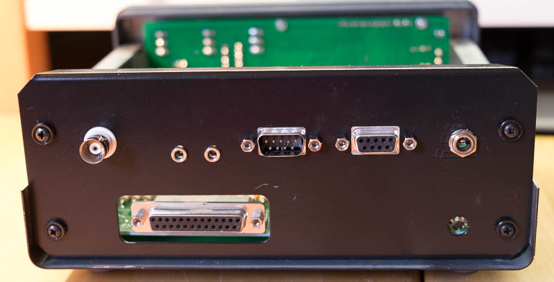
hamware AT-502/AT-515/AT-615B Interface
I've developed a small interface board for the HAMWARe controller AT-502, AT-515 and AT-651B. This interface boards supports RS232 and CI-V communications and can be directly mounted into the controller chassis.
![]()
LF-Converter
I've ordered the LF-converter BX-082 kit from the German HAM Radio magazine FUNKAMATEUR already some months ago and now found the time to build and test it.
SMD Solder Station
It all started with an article in the issue July 2014 of the German amateur radio magazine FUNKAMATEUR. Martin Kumm, DC3MKB published in this issue an interesting article for a smart SMD soldering station based on the well know ARDUINO UNO.
Connecting an Arduino to MOSQUITTO
In this post, I've showed, how to setup Mosquitto on an Windows 8 machine. Now let me describe, howto connect an Arduino via Ethernet to the running Mosquitto MQTT broker.
Getting started with MOSQUITTO
After my first experiments with 2elemtry, I decided to give MOSQUITTO a try. Mosquitto is a small MQTT message broker, which provides basically the same functionality like 2lemetry.
Here the steps, I got Mosquitto up und running on my Windows 8 machine:
CW-Sensor-Keyer
Based on the work of John, M0UKD, I've build a small sensor-keyer. I used a surplus aluminium shelf and two aluminium stand-offs as "paddles".
See the evolution of this project here.
Getting started with 2lemetry
During my researches for my home automation project I also stumbled across the MQTT protocol for sensor-server-communication. A matching arduino library was found quickly here on Nick's blog. An arduino sketch was quickly copied from here and modified. Download my version from here.
hamware AT-515 Firmware
I've created a new firmware for the hamware AT-515 tuner.
Please check a detailled description in this manual (currently German only)
*** The RAW-Mode for the interface is no longer supported ***
Some parts are available at cost price. Please check here.
Neuer DARC Image Film
Ein richtig gut gemachter Film des DARC!
- MODBUS slave
- MODBus master
- MODBus shield
- Capacitive level sensor - electrode design
- MODBus - register usage
- Capacitive (water) level sensor
- MODBus Node with level sensor
- Arduino Home Automation
- Update I2C LCD-Library for Arduino
- nanoKeyer - neue Frontplatte
- Digital-Multimeter comparision
- XPhase - Interference reduction
- hamware AT-515 - Neue Firmware
- hamware AT-502 Firmware - Erweiterung für 160m und 80m
- hamware AT-502 Firmware - Update CI-V Schnittstelle
- Splitter/Combiner - Funkamateur.de
- hamware AT-502 Firmware - IRB P02
- hamware AT-502 Firmware - K2+RUMLOG
- hamware AT-502 Firmware - Kenwood erweitert
- Zusatzschaltungen für Arduino etc.
- hamware AT-502 - Firmware
- Powermeter von DG7XO
- nanoKeyer - Extensions - 2nd
- KW-Antenne MP1
- nanoKeyer -Extensions
- Mini Morsetaste SQUEEKY
- Computergesteuerte HF-Eichleitung
- nanoKeyer - Arduino based memory keyer
- Reverse Beacon Network
- Dune HD Smart B1 + S-Video
Page 8 of 10