Last year I've build the cheap Frog Sounds QRP Transceiver. This transceiver has a pretty basic audio section - a simple LM386 audio amplifier with some LC/RC filtering.
My first QSOs were done using the excellent audio CW filter from Funkamateur. This CW filter is big, has many complex RC sections but works excellent.
I've searched the net for a not too complex audio CW filter and found the work of NM0S at the website of the "Four State QRP Group".
The kit sells for a reasonable price also to DX locations. But I decided to try a very small SMD based filter, which can also be integrated into existing QRP transceivers.
Here you can see my first version:  . Except a 78L08 voltage regulator, it is completely based on this schematic. My intention was, to protect the LM386 audio amplifier chip against high supply voltages. The standard version of the LM386 only allows 12VDC as supply current. In my shack I'm running usually 13.8VDC to get stable 100W from my K3.
I think the idea was not bad, but the implemtation was not so good. At higher audio output level, the LM386 start oscillation. I assume due to power supply problems from the voltage regulator.
I found the solution to handle the audio distortion - replace the 100nF filter capacitor near the LM386 with a 100uF electrolyth capacitor and then also the 8V regulated powersupply works well. The same I did for the version without the 78L08 voltage regulator. Now both version are working fine - with the voltage regulator the LM386 is also operated within its specs :-)
As you can see, I build the 0dB version of this audio filter. Means more or less no amplification from the circuit. Measurements shows, that the board has a small amplification level of roughly 4dB.
The fiter is pretty sharp 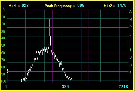 but as you can see, the filter peak is not perfectly centered in the filter shape. Also the filter peek frequency is abt. 800Hz. I assume this is due to the fact, that I'm using standard components for some resistors (33nF instead of 36nF/39nF and 33k instead of 36k).
To try, whether the audio amplifier problems is due to the usage of the 78L08 regulator, I build a second board 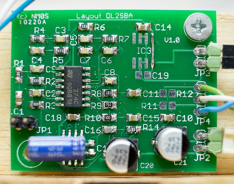 (flux not removed yet).
Here you can see, that the voltage regulator (IC3) is replaced by a simple wire and second, that the 100nF filter capacitor for the LM386 is replaced by a 100uF/25V electrolyth capacitor. Supplying the circuit with 13.8VDC now gives stable audio ouput even at high levels.
For test purposes, I mounted the filter board on a junk piece of wood, supplied two jacks for audio input/output, a 47k variable resistor and a DC power socket: 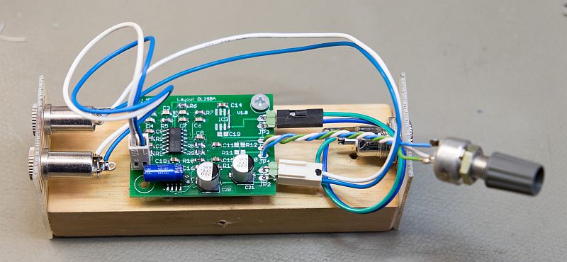 .
.
Next steps is to put the amplifier into an aluminium case with good input/ouput jack, volume control and DC jack.
I have some spare boards - please check my Sale page.
2016-05-05: Read on what happens to the filter-board next.