I've planned to sell my ELECRAFT K2 so I placed some adds in the various HAM sources and I found a buyer willing give my K2 a new home.
Fortunately I decided to do a quick check on the K2 functions, to be sure, that the buyers receives a full functional K2.
I did the check in the late afternoon on 80m and I was shocked - strong stations can be received every 7kHz. Testing the transmitter shows a totally unstable RF signal.
Initial measurement and realignment according to the K2 manual shows no results. Also removing all installed options and replacing them with "Rework Eliminators" shows no success.
What to do now - my last idea was, to hook up my ELAD SDR S2 to the testpoints inside the K2.
FIrst I checked TP3 - the output of the PLL reference oscillator: 
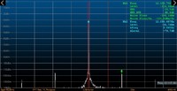
The signal shows a clear signal at 12MHz and spikes within 7kHz distance to the main carrier but with an attenuation of abt. 80dB - this looks fine.
Now I hooked up the SDR to the output of the VCO at TP1 and it looks worse:  .
.
Here you can again see these 7kHz. But here the attenuation was only abt. 12dB. Checking the DC voltage levels at the VCO buffer shows no big differences to the values stated in the K2 manual.
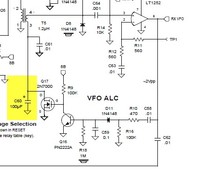
Completly frustated I wiggled all parts of the VCO buffer. And hey, the 100uF capacitors show a little bit strange tactile feedback: 
Heating up the soldering iron and after a short resoldering, the capacitors now sits firmly in the PCB and the transmitter output is fine again  without these 7kHz harmonics.
The missing 100uF capacitor allowed the VCO ALC to oscillate with abt. 7kHz which led to the strange behaviour on receive as well as during transmissions.
Conclusion- you can use a modern direct sampling wideband SDR also as a bandwidth limited spectrum analyser!
