Here are the first pictures of my KiwiSDR setup ...
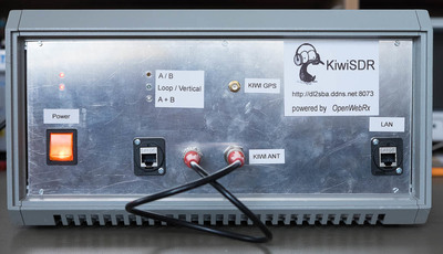
Front view
I've used an old, but extremly sturdy 19" case from Schroff - good ventilation - a little bit to large but enough room for extensions ;-)
The shown frontpanel will be finished, when all internal stuff is completed - so the labels etc. are interim.
The BNC cables bridges the LZ1AW antenna output to the KiwiSDR antenna input.
From left to right:
- power switch with LED power indicators for +12VDC and +5VDC
- RJ45 socket for LZ1AQ loop with LED indicators for operation mode of loop
- BNC socket for output from LZ1AQ loop
- BNC socket for RF antenna input to KiwiSDR
- SMA socket for external active GPS antenna to KiwiSDR
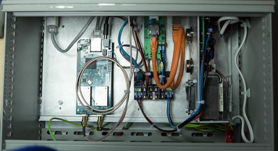
Top view
From left to right:
- KiwiSDR
- LZ1AQ loop controller
- Interface LZ1AQ antenna controller and KiwiSDR
- Linear power supply HAA512-AG from Bel Power solutions. It provides +5VDC@2A and +12VDC@0,5A
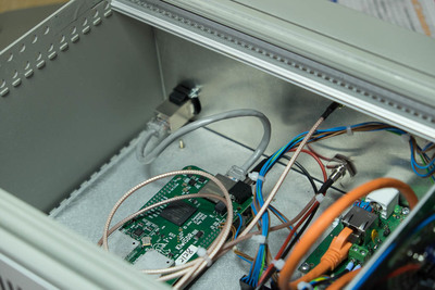
Top view #2
From left to right:
- Shielded RJ45 socket from CLIFF
- KiwiSDR. The LAN line between the RJ45 socket and the KiwiSDR will be replaced later with a shielded one.
- SMA socket for external active GPS antenna to KiwiSDR
- LZ1AQ loop controller
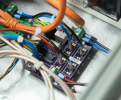
Interface for LZ1AQ antenna controller
Interface- and power distribution board. For details check here.
