Here are some technical details for my KiwiSDR setup ...
Power supply
As recommended on the KiwiSDR website I've used a linear type power supply. As I didn't want an external power supply, I go for the Bel Power Solution HAA512-AG.
This is a professional power supply with all relevant certifications (even for medical use). It's not high-tech - simple LM723 linear regulators with 2N3055 power transistors.
The 12V rail is adjustable between 12VDC and 15VDC so I can compensate longer connection wires to the external loop amplifier.
The linear power supply ensure a low noise level for the KiwiSDR - more details will come. BTW - I've started a discussion on the KiwiSDR forum.
Interface KiwiSDR/LZ1AQ controller
Kari OH1KK has implemented a plugin for the OpenWebRX to control antenna switches. I'm using this extension to controll the LZ1AQ loop modes via this plugin.
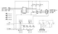
For a simple interface I've created a small PCB for power distribution (+5VDC, +12VDC), relay interface from KiwiSDR to LZ1AS controller and some LEDs.
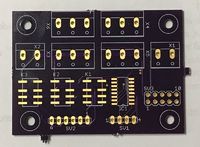
In the meantime the PCBs arrived and I've build up one. Please find the circuit diagram and a picture of the PCB below:
The board is mainly populated with SMD devices - resistors, capacitors, ULN2003 and relays. The headers and screw terminals are through-hole components. At all no problem to build.
- The KiwiSDR cape is connected via its P8 connector to the 4-pin header SV1 on the interface board. Unfortunately you have to solder the four wires on the connector pins on the cape. I think a mirrored P8 on the cape would be very usefull for extensions ...
- The LZ1AQ controller is connected via its standard 6pin header with header SV2 on the interface board.
- Header SV3 provides a convenient way to connect +5DC and +12VDC power supply LEDs as well as indicators for the three switches of the LZ1AQ controller.
If someone is interested in such a board - I have one spare board - I can provide it at cost price. Please check my Sale page.


