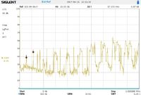
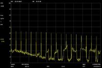
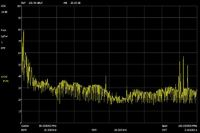
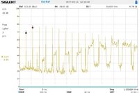
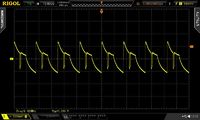
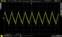
I've used one of these cheap switch-mode DC-DC converters (available on eBay for a few bucks) for my WSPR U3S transmitter. Checking the transmitted signal reveals strong spurious emissions. Hints from the QRPLabs group leads me to the cause - the DC-DC converter. Replacing it with a linear LM317 one solves the problem.
Spectrum analysis
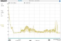
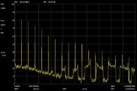
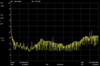
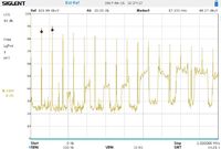
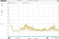
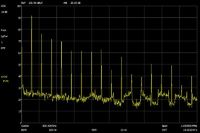
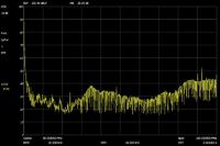
To get an idea on the output quality of this switch-mode DC-DC converter, I hocked it up to an SIGLENT SSA3021X spectrum analyzer. The converter was fed with 13.9VDC from a linear regulated bench power supply. As load I've used Re:load Pro I bought some years ago on KickStarter.
To protect the input of the spectrum analyzer, I've put an 1.5nF foil capacitor in series with the analyzer input for some measurements.
| Load | Scan width 1MHz | Scan width 100MHz | Scan width 1MHz | Scan width 100MHz |
| 1.5nF capacitor in series | 1.5nF capacitor in series | direct connect | direct connect | |
| 0mA |
Peak voltage ~2.5mV |
|
|
|
| 100mA |
Peak voltage ~ 10mV |
|
|
|
| 1.000mA |
Peak voltage ~35mV |
|
|
|
Now the question is, why do these 10mV riples (you can see the switch-mode converters frequency 56kHz) have such big effects on the output of the DDS on the U3S main board?
Scope measurements
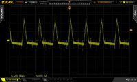
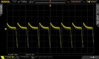
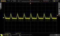
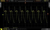
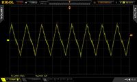
Next round - connect a digital oscilloscope with a 1:10 test head to the switch-mode DC-DC converter. The channel is bandwidth-limited to 20MHz with AC coupling.
| load | input terminal | output terminal | input terminal | output terminal |
| Bench power supply | Bench power supply | LiFePo accu | LiFePo accu | |
| 100mA |
Here we now have ~200mV peaks |
|
Even a little bit more ~230mV |
|
| 1.000mA |
Is this load regulation of the bench power supply? |
More load things get worse ~430mV
|
Hm - even with thick cables and big power pack!? |
A litle bit less ~400mV
|
