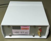
Based on the work of Makis, SV1AFN i've build a small, stand-alone power meter with a "nice" GUI. This is the second RF head I've received from Makis. Data about the first one can be found here. 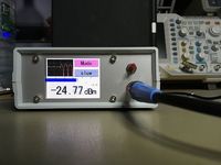
Construction
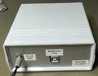
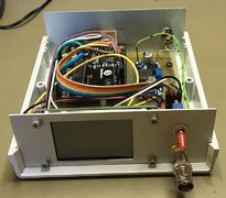
The housing is a cheap TEKO box, I bought during last years visit to the HAM RADIO fair in Friedrichshafen.
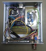
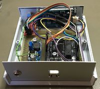
Inside resides an arduino clone, a DC/DC converter, the power-sensor head and the display.
The wiring is crappy, it will be replaced with permanent cables when I find some time.
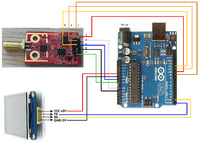
Schematic
User interface
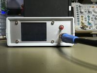
The user interface for the powermeter is pretty simple. An On/Off power switch, the SMA socket for the input power and the LCD touch display. Next you can see the screens of the UI:
Splash screen druing power-up: 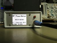
Main screen:  The displays shows the following information (from top to bottom):
- A simple scrolling diagram showing the relative input power over time
- A button to switch into setup-mode
- A button to toggle between fast/slow samplling mode
- A bar graph showing the actual relative power.
- A hairline below the bar graph showing the last peak value (peak-hold)
- The peak-hold numerical value
- The actual relative input power
Setup screen: 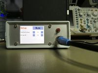 On this screen, you can adjust the decay time of the peak-hold function as well as the buffer-depth for the moving average function.
Video
Please check the video where you can see the powermeter in action: YOUTUBE
Libraries
AD7887
The ADC is read using my simple AD7887 library and some code. You can find the current source code on GITHUB. Place all files in a subfolder named "RFPowerMeter_Next_V3" inside you Arduino sketch folder.
Nextion Display
I have changed the used Nextion library a little bit - for performance reasons and because some stuff didn't work for me. Please check my changes here.
Contact
If you have any questions, please contact me by Diese E-Mail-Adresse ist vor Spambots geschützt! Zur Anzeige muss JavaScript eingeschaltet sein!.

