Some times ago, I found for me a solution, how to handle the unstable readings from the ADC. I've described it in this post.
In the meantime, some HAMs also build the RF powermeter based on the work of Makis, SV1AFN and myself. One if these HAMs, PA3AXA Rens, digged a little bit deeper and analysed the problem in detail. Here his description.
PA3AXA Rens
I've tested on 3 different type of Adruino, all chineese clones but the behavior was the same. When I used the typical Chinese ribbon cable to connect the CS/CLK/MISO/MOSI I would measure just no pulses at all on the MISO pin. Then I just ripped the ribbon cable apart in single wires, lying losely on the table, the powermeter started working.
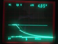
Measuring on the Arduino, it would look like this:
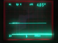
The waveform below an extra 22k to GND on the AD8313 board was added:
Then I found out, that bringing CLK and MISO wires together, still influences the pulses seen on the scope. Adding 100 Ohm in series with the MISO line at the Arduino side cured that problem. So now it is "rock solid", no matter what you would do with the connecting wires.
Did not go all the way back to use a ribbon cable again with these extra resistors in place. The 22k to GND on SCLK might be not needed either, but I left in place.


