Some weeks ago I've build a full-featured XPhase for my father, DK1UO. He is sometimes affected by heavy interference from Plasma-TVs or similar scrap
The function of the XPhase is based on the fact that the interfering signal, received by an auxiliary antenna, is added phase-shifted to the signal received from the main antenna. When the phase-shift is more or less 180°, the interfering signal is canceled out.
My XPhase is based on the work of Hanns, DK9NL. A commercial versions can be found here under the name QRM-Eliminator. Google will provide you some futher informations.
As usual Dirk, DH4YM provided excellent PCBs for a more than fair price - thanks for this Dirk. I've bought all the parts at my preferred supplier Reichelt. Except the FET J310, everything can be found at Reichelt. The required J310-FET can be found i.e. at Funkamateur online-shop.
Input protection
The XPhase provides a simple input protection for the FETs using pairs of 1N4148 diodes.  image (c) DK9NL
These diodes can cause distortion with strong input signals. I suggest to replace each single 1N4148 with a couple of series connected 1N4148 to enhance immunity against strong input signals. These twin-diodes can be seen here 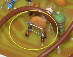
VOX circuit
The full-featured XPhase basically supports the usage with a shortwave transceiver. The integrated VOX is more than a simple solution, so I suggest always to use the PTT-interface. The default PTT-interface uses 1N4148 diodes which can cause trouble. 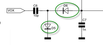 image (c) DK9NL
Receive-only version
I'm running a K3 with the integrated XVerter board KXV3A in my shack.
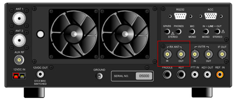 image (c) ELECRAFT
The transverter board board provides an easy way to integrate the XPhase in the RX-path of the K3. Simply connect the main-antenna input of the XPhase to the RX-Ant-Out port and the RX-Ant-Inp port of the Xverter-interface to the RX port on the XPhase. Now you can easily switch the XPhase in and out from the reciever path using the RX-ANT push-button  on the front-panel of the K3. As a logical consequence, there is no need for the RX/TX switching inside the XPhase, as there will be never any transmission through the XPhase. As you can see, therefor the parts on the pcb are greatly reduced
 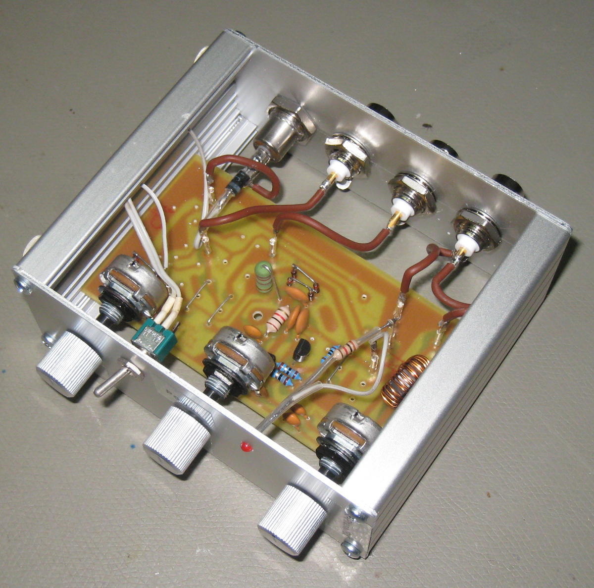 when using it in RX-only mode.
Housing
The casing I'm using has more or less the same height like the K3 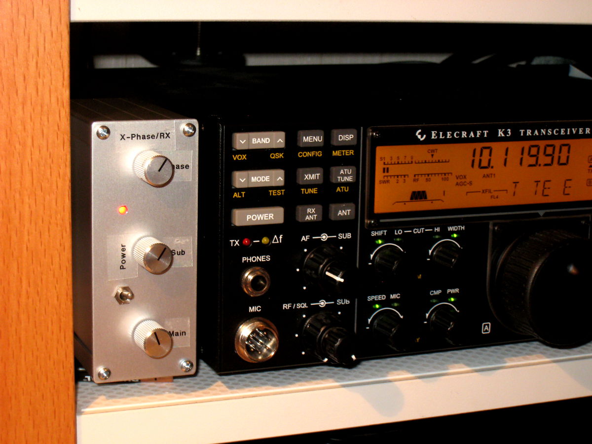 - only the colour matching needs some improvement ;-)
More views 
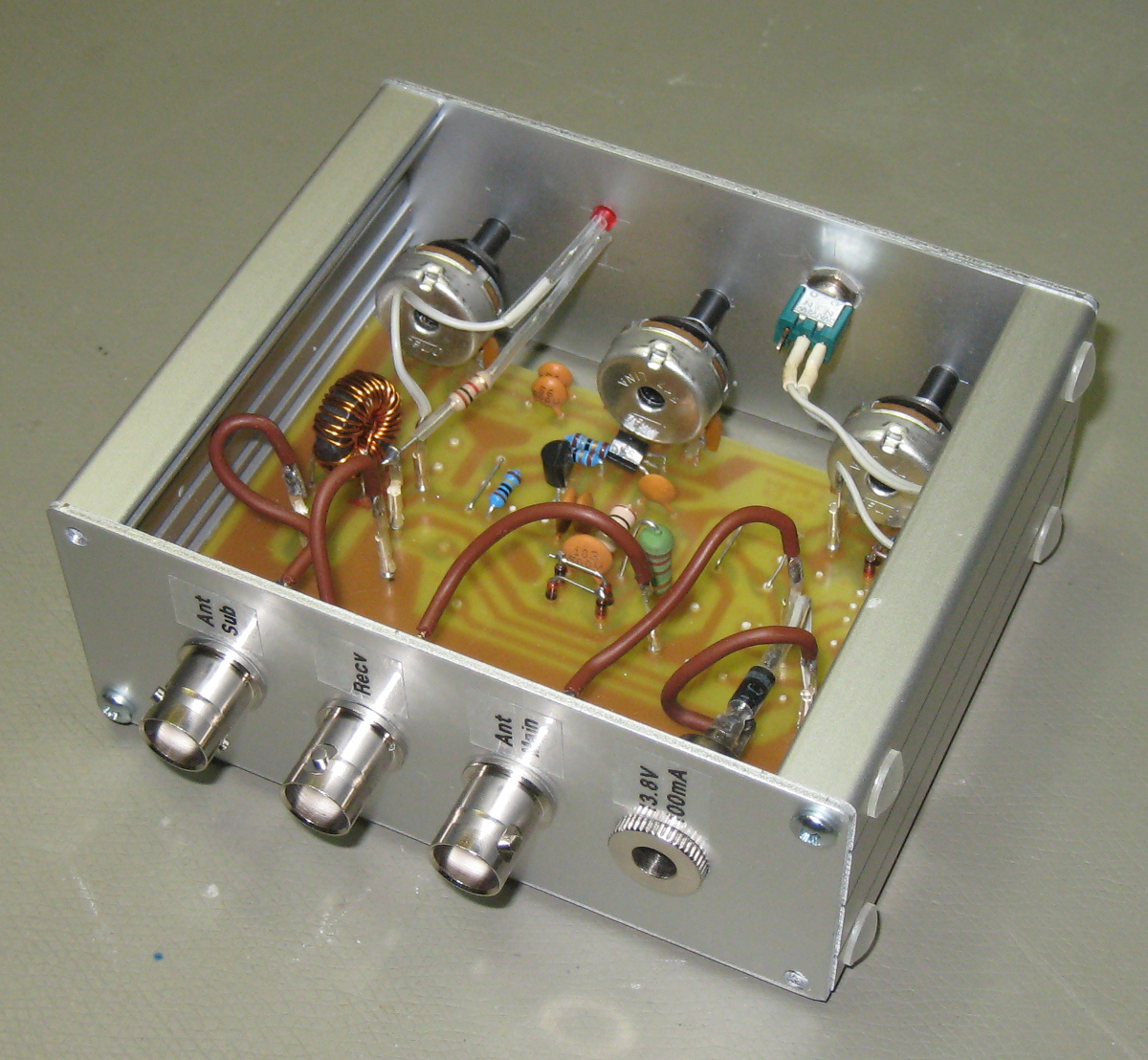
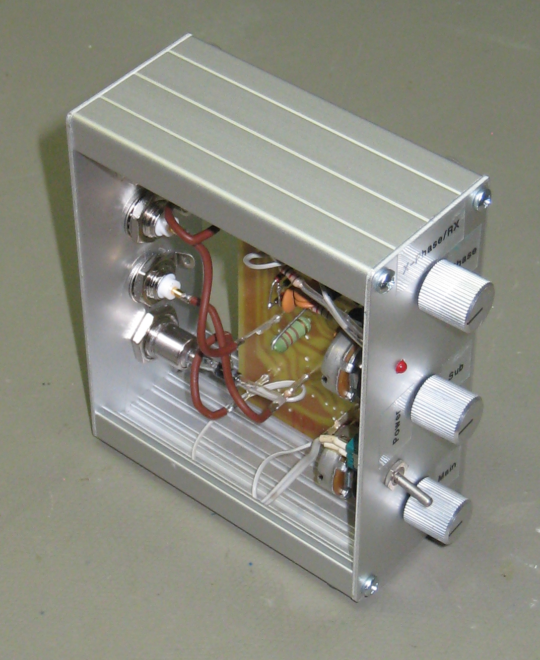
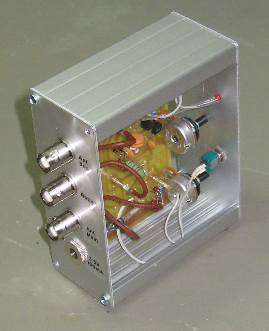
The housing is a halved version of the EURO-1 housing cut on my little circular saw from Proxxon.
Measurements 1 MHz - 56 MHz
This XPhase uses the FT50-43 torroid instead the original FT50-77 - this should give better performance on 10m and above.
To do some basic measurements, I've hooked up my miniVNApro to the XPhase to measure ...
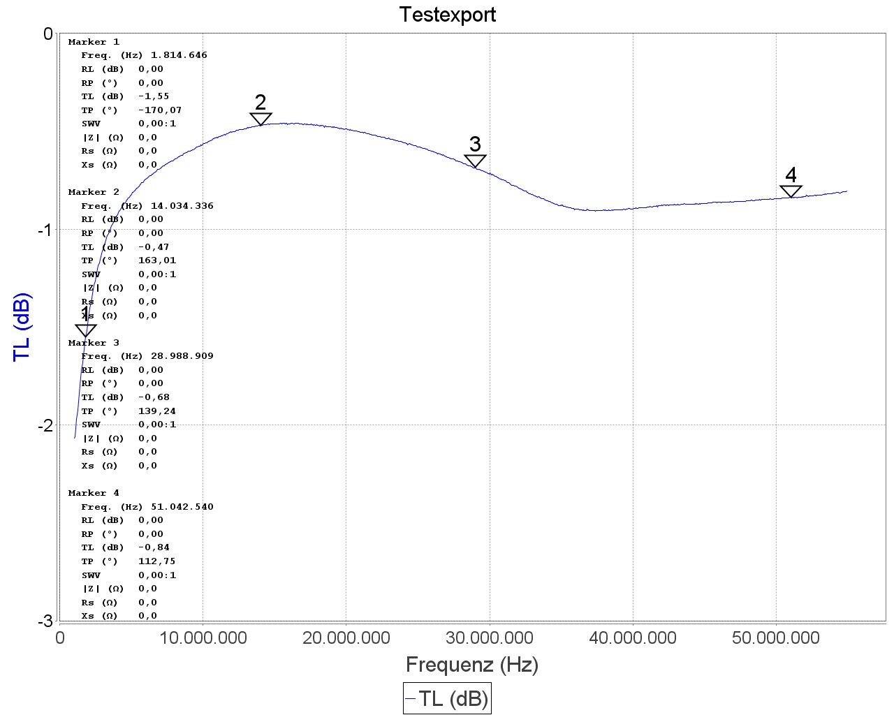
Receive attenuation
- 50Ohm terminator on aux-antenna connector
- vna DET input on rx connector
- vna DUT output on main-antenna connector
- Gain 1 - fully clockwise
- Gain 2 - fully counter-clockwise
- Phase - fully counter clockwise
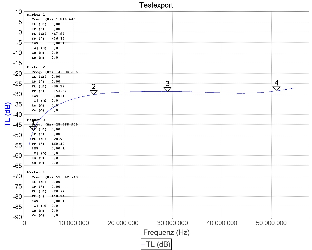
Receive isolation
- 50Ohm terminator on aux-antenna connector
- vna DET input on rx connector
- vna DUT output on main-antenna connector
- Gain 1 - fully clockwise
- Gain 2 - fully counter-clockwise
- Phase - fully counter clockwise
Power off
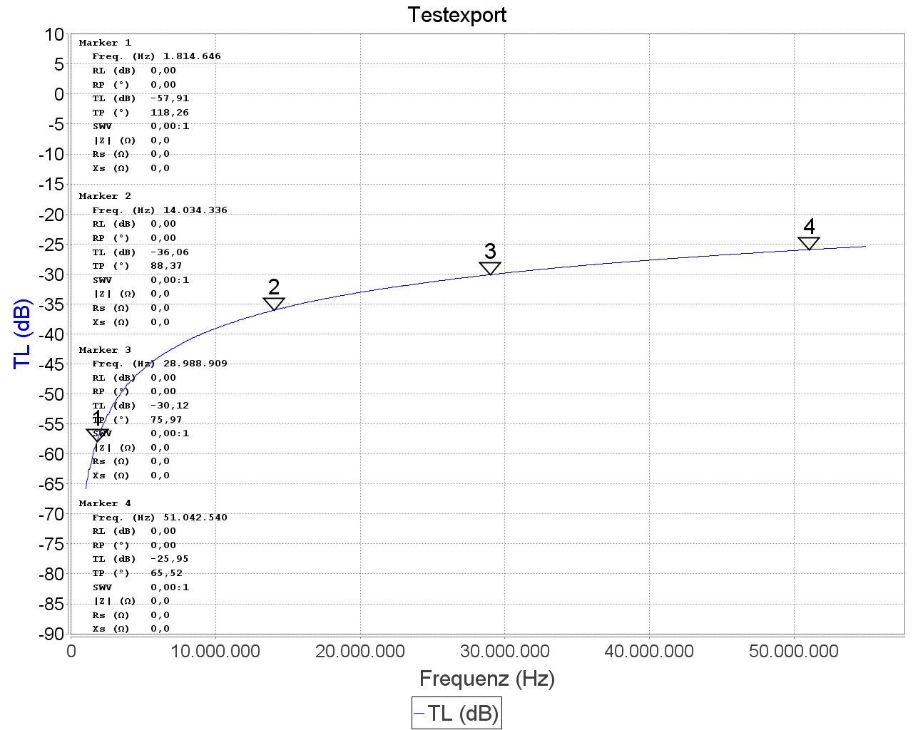
Some DC parameters here:
- Supply current at 12.145 VDC is 70.00mA
- Voltage at L1/T2/T2 is 4.55VDC
- Voltage at C4/R2 is 0.51VDC
- Voltage at C5/R3 is 0.52VDC
Images (c) DK9NL & Elecraft.com & DL2SBA