In this post I describe in details, how you can create the calibration factors for k0 ... k3 based on raw data measured with the power sensor.
Center is this XLS file. Relevant are lines 14-24.
-
Column A "Target" contains the power provided by the generator in dBm. These must be either in descending or ascending order.
-
Column B "Cnt" contains the raw value from the ADC (therefore we have this third screen in V1.7.1) when the power in Column A is provided to the sensor
-
Column C contains the corrected values based on the factors k0-k3
-
Column D shows the absolute difference to the generator output level
So now, how to get the factors k0-k3?
-
Download the Excel
-
Enter you RAW data values in the cells B14 to B24
-
Enter the displayed factor X3 in the lower diagram into cell B11
-
Enter the displayed factor X2 in the lower diagram into cell C11
-
Enter the displayed factor X in the lower diagram into cell D11
-
Enter the constant in the lower diagram into cell E11
-
Check the deviation from the ideal line in the upper diagram
-
Copy the calculated factor into the constants table in this sketch file data.cpp
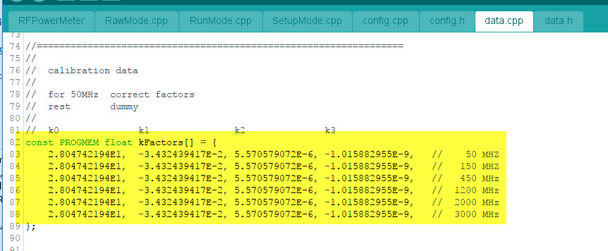
- Upload the recompiled sketch to the Arduino.
More details from F6ITU
Marc F6ITU has provided a more detailled description how to do the calibration on his website.